
Injection Mold Tolerances: What ±0.02 mm Really Means and How to Specify Them
Understanding DIN 16742 tolerance grades, what is actually achievable in production vs. what is aspirational, how tolerance specifications drive mold cost, and how to write a tolerance callout that does not waste money.
A procurement manager at a European Tier 1 supplier sent us an RFQ for a PA66 GF30 engine bracket. The drawing called out ±0.02 mm on every dimension ”” roughly the thickness of a human hair split in half. The part was 240 mm long. We asked whether the tolerance was truly functional or carried forward from a metal machining drawing. After a week of internal review, the answer came back: only three of the eighteen dimensions actually required ±0.05 mm or better. The remaining fifteen could be held at ±0.15 mm or wider. The mold cost estimate dropped by roughly 23%. The program moved forward.
This scenario ”” tolerances specified tighter than the application requires, often inherited from machined metal part drawings or from a well-intentioned but uninformed "tight is better" assumption ”” is one of the most common and most expensive errors in injection mold procurement. Understanding what is actually achievable, what different materials can deliver, and how to write a tolerance specification that is both functional and manufacturable is essential knowledge for anyone buying an injection mold.
Tight tolerances do not automatically produce better parts. They produce more expensive molds, longer lead times, higher scrap rates, and more inspection cost ”” whether or not the tolerance was actually needed.
What controls achievable tolerance in injection molding
Injection molding is not machining. The plastic shrinks as it cools, and it shrinks differently in different directions, at different rates depending on wall thickness, and to different final dimensions depending on processing conditions ”” even in the same mold cavity. A tolerance that was held on Tuesday's production run may drift on Wednesday if the ambient humidity changed or the regrind percentage shifted. Understanding the physics is the first step to writing a realistic tolerance specification.
Six factors interact to determine what tolerance is achievable on any given dimension:
Every thermoplastic shrinks as it solidifies ”” from ~0.2% (PBT GF30) to ~2.5% (unfilled PP). This is the single largest variable. Lower and more consistent shrinkage = tighter achievable tolerances. Glass-reinforced grades shrink less and more predictably than unfilled grades.
Tolerance is proportional to dimension. A ±0.05 mm tolerance on a 10 mm feature is realistic. The same tolerance on a 500 mm panel is not ”” the absolute shrinkage variation over 500 mm exceeds the tolerance band regardless of process control. This is literally physics, not a capability limitation.
Differential cooling from non-uniform wall sections produces differential shrinkage ”” which resolves as warpage and dimensional variation. A part with 3:1 wall thickness variation will never hold the same tolerance as a part with uniform walls, regardless of mold quality.
The mold cavity itself has tolerances. A cavity machined on a high-precision CNC with final EDM finishing can hold tighter part tolerances than one built on older equipment. Tool steel selection (hardened vs. pre-hardened) affects long-term dimensional stability as the mold wears over hundreds of thousands of cycles.
Melt temperature, mold temperature, hold pressure, hold time, cooling time, and material moisture content all affect final part dimensions. A mold that can hold ±0.05 mm in a production cell with closed-loop process control may only hold ±0.15 mm in a less controlled environment. The mold is only part of the system.
Nylons (PA6, PA66) absorb moisture after molding and grow dimensionally. Parts measured immediately after molding will be different sizes 24 hours later after conditioning. For PA parts requiring tight tolerances, conditioning and measurement protocols must be specified ”” otherwise the tolerance is meaningless.
DIN 16742: the standard tolerance framework for plastic molded parts
DIN 16742 (harmonized as ISO 20457) defines tolerance groups for plastic molded parts based on material shrinkage characteristics and part size. It is the most widely referenced standard in automotive injection mold procurement, and understanding its structure is essential for writing a tolerance specification that a mold maker can actually work to.
| Tolerance group | Material examples | Shrinkage range | Typical achievable tolerance (100 mm dimension) | Relative mold cost impact |
|---|---|---|---|---|
| TG1 ”” Very precise | PBT GF30, POM, PC GF30 | < 0.5% | ±0.05 ”“ 0.10 mm | Highest ”” requires optimized tool construction, tight process control, and more complex cooling |
| TG2 ”” Precise | PA6 GF30, PA66 GF30, ABS, PC/ABS | 0.5 ”“ 1.0% | ±0.08 ”“ 0.15 mm | Moderate ”” standard precision automotive mold construction |
| TG3 ”” Normal | PA6 unfilled, PP-GF20 | 1.0 ”“ 1.5% | ±0.12 ”“ 0.25 mm | Standard ”” commercial mold construction |
| TG4 ”” Coarse | PP unfilled, PP-TD20, PE | 1.5 ”“ 2.5% | ±0.20 ”“ 0.40 mm | Lowest ”” simplest tool construction; widest processing window |
Note that tolerance is proportional to nominal dimension. The values in the table are for a ~100 mm feature. For a 500 mm feature in the same material, the achievable tolerance is roughly 2”“3× wider. This proportionality is built into the DIN 16742 tables and should be reflected in every tolerance callout ”” specifying the same absolute tolerance on every dimension regardless of size is a red flag that the tolerance was not derived from a functional requirement.
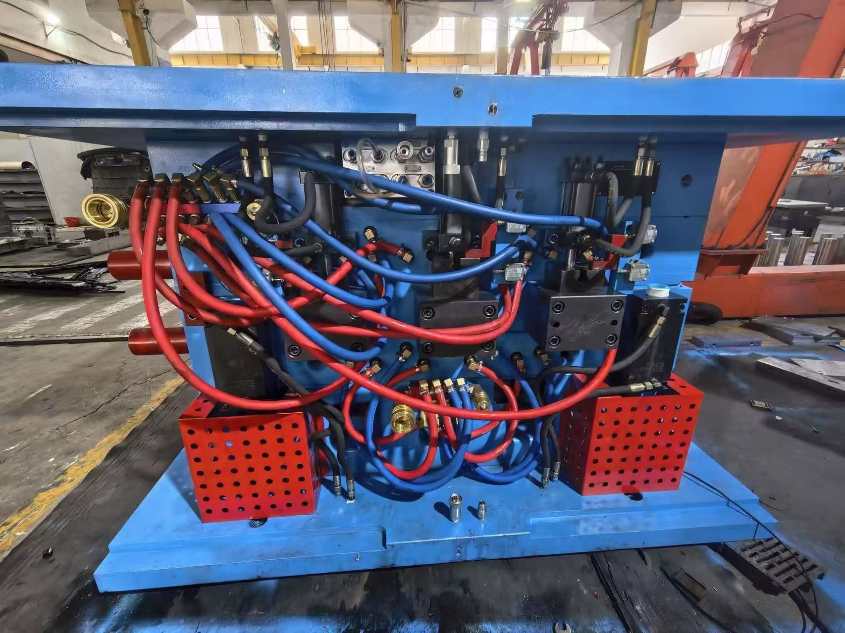
How tolerance drives mold cost ”” the real numbers
The relationship between specified tolerance and mold cost is non-linear. Tightening tolerance from TG3 to TG2 typically adds 10”“15% to tool cost. Tightening from TG2 to TG1 can add 25”“40% ”” and in some geometries, the premium is higher because it requires a fundamentally different tool construction approach.
Here is what changes in the mold as tolerance tightens:
- TG4 → TG3 (coarse to normal): Standard pre-hardened tool steel, conventional cooling layout, standard gate design. The incremental cost is modest ”” mostly additional machining time for tighter cavity dimensions.
- TG3 → TG2 (normal to precise): Hardened tool steel may be required for wear-critical surfaces. Cooling circuits must be more carefully routed to maintain temperature uniformity. Gate sizing and placement require mold flow analysis to predict and compensate for anisotropic shrinkage. Cavity dimensions are machined with tighter tolerances on the mold itself, often requiring EDM finishing passes. Inspection at T1 is more extensive.
- TG2 → TG1 (precise to very precise): Fully hardened tool steel (typically 50”“54 HRC), conformal cooling often required, multiple mold flow iterations to optimize gate location and process window, cavity dimensions verified by CMM at intermediate machining stages ”” not just at final inspection. The mold build time increases by 2”“4 weeks. Every surface that touches the part is a precision surface.
The most expensive tolerance on any part print is the one that is tighter than the application requires ”” and was never questioned.
How to write a tolerance specification that doesn't waste money
Based on hundreds of mold programs, here is the approach we recommend to every customer before tool build begins:
1. Classify every dimension by functional criticality
Not all dimensions are equal. A datum surface that locates a seal or mates with another part at assembly is functionally critical. A cosmetic surface that is visible but non-functional has a different tolerance requirement. A non-functional clearance surface has yet another. Label each dimension on the print: critical (tight tolerance required for function), significant (standard precision), or reference (wide tolerance acceptable). Then apply tolerances by classification, not uniformly.
2. Specify tolerances with the material in mind
A ±0.05 mm callout is realistic for PBT GF30. It is aspirational for unfilled PP. The material selection section of this site has more detail ”” but the principle is: write the tolerance against what the material can deliver, not against what the steel cavity can theoretically be machined to.
3. Use GD&T datum references, not linear ± on every dimension
A well-constructed GD&T datum reference frame ”” typically three mutually perpendicular planes established from functional part features ”” defines how the part is located in the inspection fixture and in the assembly. It is more representative of real-world function than a list of linear dimensions with identical ± tolerances. It also tells the mold maker which surfaces are the priority for precision ”” the datums and the features referenced to them ”” rather than treating every surface as equally critical.
4. Include conditioning and measurement protocol for moisture-sensitive materials
For PA6 and PA66 parts: specify whether dimensions are to be measured dry (immediately after molding), conditioned (after moisture equilibration at 23°C / 50% RH), or both. A part that meets tolerance dry may be out of tolerance conditioned ”” and vice versa. The protocol must be agreed before tool build, not debated after T1 samples are measured.
5. Ask: what actually happens if this dimension is out of tolerance?
If the answer is "the part won't assemble" or "the seal will leak" or "the snap-fit won't engage" ”” the tolerance is justified. If the answer is "we've always specified it this way" or "tighter is better" ”” the tolerance is worth revisiting. Tightening a tolerance that has no functional consequence adds cost with zero value. Every dimension on the print should survive this question.
Real-world tolerance capability by material and dimension
The table below represents what Gege Mould delivers in series production with good DFM, modern CNC/EDM equipment, and consistent process control. These are achievable values ”” not guaranteed minimums, and not theoretical limits. Individual geometries may vary. A deep-draw rib with high aspect ratio will not hold the same tolerance as a simple flat surface in the same material.
| Material | ≤ 30 mm feature | 30”“100 mm feature | 100”“300 mm feature | 300”“600 mm feature |
|---|---|---|---|---|
| PBT GF30 | ±0.03 ”“ 0.06 mm | ±0.05 ”“ 0.10 mm | ±0.10 ”“ 0.18 mm | ±0.18 ”“ 0.30 mm |
| POM | ±0.04 ”“ 0.07 mm | ±0.06 ”“ 0.12 mm | ±0.12 ”“ 0.20 mm | ±0.20 ”“ 0.35 mm |
| PA6 GF30 / PA66 GF30 | ±0.04 ”“ 0.08 mm | ±0.06 ”“ 0.14 mm | ±0.12 ”“ 0.22 mm | ±0.20 ”“ 0.38 mm |
| ABS / PC/ABS | ±0.05 ”“ 0.09 mm | ±0.08 ”“ 0.16 mm | ±0.14 ”“ 0.26 mm | ±0.24 ”“ 0.42 mm |
| PA6 unfilled / PA66 unfilled | ±0.06 ”“ 0.10 mm | ±0.10 ”“ 0.20 mm | ±0.18 ”“ 0.32 mm | ±0.30 ”“ 0.55 mm |
| PP-GF20 / PP-GF30 | ±0.06 ”“ 0.12 mm | ±0.10 ”“ 0.22 mm | ±0.18 ”“ 0.35 mm | ±0.30 ”“ 0.55 mm |
| PP unfilled | ±0.08 ”“ 0.15 mm | ±0.14 ”“ 0.28 mm | ±0.24 ”“ 0.45 mm | ±0.40 ”“ 0.70 mm |
Values are empirically derived from production data. They represent what a well-designed, well-built, and well-operated mold can deliver ”” not what every mold will deliver under every condition. Use as a guideline, not a guarantee. Individual part geometry always governs.
The Gege Mould approach: tolerance review before tool design
On every program we receive, tolerance review is one of the first engineering activities ”” before cooling design, before gate placement, before any steel is ordered. The process:
- Classify every dimension by functional criticality (critical / significant / reference)
- Cross-check the tolerance specification against the material ”” flag any callout that is not realistically achievable in the specified material at the given feature size
- Identify the dimensions that drive tool cost ”” typically the tightest 2”“5 tolerances on the print, which often dictate tool steel grade, cooling complexity, and inspection scope
- Present the trade-offs to the customer before tool build ”” "these three dimensions at ±0.03 mm add roughly 18% to tool cost and 2 weeks to lead time. Are they functionally required? If yes, we build to them. If not, here is what relaxing to ±0.08 mm saves."
If you are planning an injection mold program and want an independent tolerance review of your part print before going to tool ”” identifying which dimensions will drive cost and which can be relaxed without functional impact ”” our engineering team is available to work through the analysis with you. Getting the tolerance specification right before tool build is one of the highest-return engineering activities in injection mold procurement. It costs nothing relative to the tool, and the savings can be substantial.

Ready to Discuss Your Mold Program?
Send us your part drawing or CAD file. Our engineering team will review it and respond with an initial assessment within 48 hours.
Get a Free Quote