
Case Study: SMC Compression Mold for Truck Exterior Panel — Large Format
How Gege Mould engineered a large-format SMC compression mold with uniform 180°C thermal control — reducing warpage from 4.2% to under 0.3% and delivering 50,000 cycles with zero rework.
The Challenge
A manufacturer of heavy-duty truck exterior components needed a large-format SMC (Sheet Molding Compound) compression mold for a next-generation exterior body panel. The part measured 920 × 680 mm — among the largest SMC panels in the customer's product range — requiring uniform 180°C cavity surface temperature across the entire molding surface. Dimensional stability was critical under 1,200-ton press clamp force, as even minor deflection in the mold base would translate directly to out-of-tolerance part dimensions. The customer's previous SMC tooling supplier had struggled with inconsistent heating, resulting in cure variation and unacceptable warpage rates on production parts.
Constraint 1 — Thermal Uniformity Across a Large Surface. Maintaining 180°C ±3°C across a 920 × 680 mm molding surface is a non-trivial thermal engineering challenge. Cold spots lead to incomplete SMC curing and weak laminate properties. Hot spots cause premature curing before full mold closure (scorch) and surface defects. The previous supplier's heating channel layout produced temperature variations of ±12°C — four times the acceptable range — directly causing the 4.2% warpage rate the customer was experiencing.
Constraint 2 — Structural Rigidity Under 1,200-Ton Clamp Force. SMC compression molding applies the full clamp tonnage directly to the mold during the curing cycle — unlike injection molding where clamp force primarily resists injection pressure. Under 1,200 tons, even a large mold base will deflect if not structurally engineered for the load. Deflection of as little as 0.10 mm across the parting line creates flash, dimensional variation, and accelerated wear at the shear edges.
Constraint 3 — Abrasive Material Flow at Shear Edges. SMC material flows across the mold surface during compression, creating abrasive conditions at the shear edges where the two mold halves close. Standard P20 tool steel wears at these edges over time, leading to progressive flash and dimensional drift. The shear edge material needed to withstand 50,000+ compression cycles without measurable wear.
Our Approach
Thermal FEA: Designing Heating Channels for ±3°C Uniformity
Gege Mould engineered the heating channel layout using thermal FEA simulation to achieve a consistent 180°C ±3°C across the entire 920 × 680 mm molding surface — critical for uniform SMC curing and to prevent the warpage issues that had plagued the previous supplier's tool. The simulation modeled oil flow rate, channel diameter, circuit routing, and proximity to the cavity surface to predict the steady-state temperature distribution. An optimized circuit routing with balanced flow — using a serpentine pattern with progressively tighter pitch near the cavity extremities where heat loss to the mold base was highest — ensured no cold spots at the edges. The final design achieved a predicted temperature variation of ±2.1°C, which was validated during in-house tryout with thermocouple measurements confirming ±2.8°C — well within the customer's ±5°C specification.
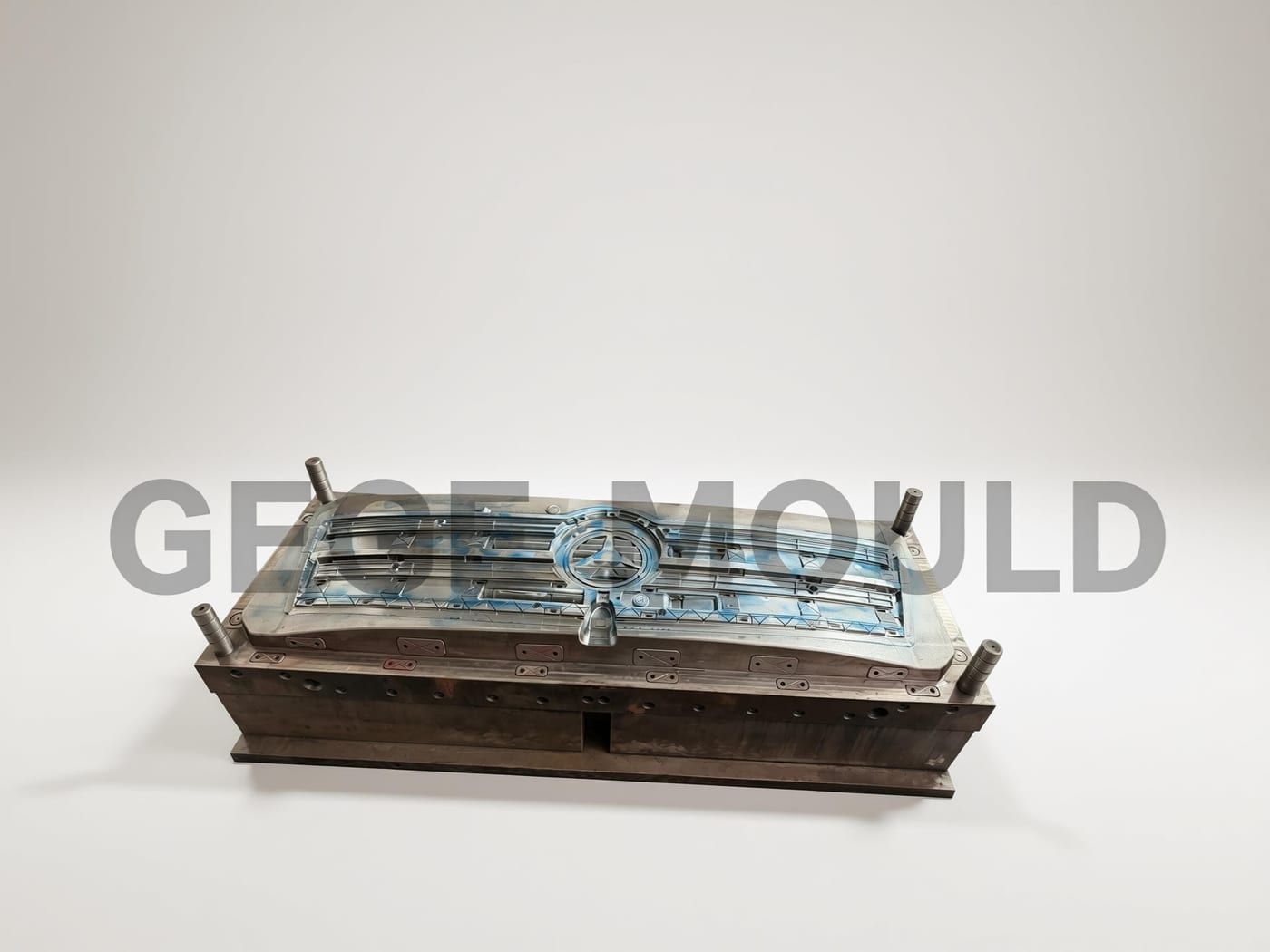
Structural Engineering: Resist 1,200 Tons Without Deflection
The mold base was structurally reinforced with additional support pillars positioned at FEA-predicted deflection nodes, and a guided ejection system to resist deflection under the full 1,200-ton clamp force, maintaining parallelism between the moving and fixed halves throughout the compression cycle. The support pillar layout added 12 pillars beyond the standard configuration, positioned specifically where the FEA model predicted maximum bending stress in the mold base — concentrated at the unsupported center span of the 920 mm cavity length. Each pillar was preloaded to ensure load transfer at zero deflection, eliminating the gap that typically exists between support pillars and the clamp plate in conventionally designed molds.
Shear Edge Strategy: Hardened Inserts Where It Matters
Rather than building the entire mold from hardened tool steel — which would have added significant cost and lead time — Gege Mould used P20 tool steel as the primary material with hardened H13 inserts at all high-wear shear edges where the SMC material flow would create the most abrasive conditions during compression. The inserts were designed as replaceable wear components, allowing the customer to swap them during scheduled preventive maintenance without removing the entire mold from the press. This modular approach balanced upfront tooling cost with long-term serviceability — a strategy that proved itself when the tool reached 50,000 cycles with the original inserts still in spec.
The Results
What This Program Taught Us
- Thermal FEA is not optional for SMC tooling. The difference between ±2.8°C and ±12°C temperature uniformity is the difference between a 0.3% and a 4.2% warpage rate. The simulation cost is negligible compared to the production scrap it prevents. Every SMC compression mold should have its heating circuit designed via thermal FEA — no exceptions.
- Modular wear components are the right strategy for compression tooling. Building the entire mold from hardened steel is expensive. Building it from standard steel and replacing cavities when they wear is more expensive in the long run. Replaceable hardened inserts at the known wear points — shear edges — gives you the best of both: moderate upfront cost, long service life, and maintainable without full tool removal.
- Structural FEA on the mold base is as important as thermal FEA on the cavity. Under 1,200 tons, a conventionally designed mold base will deflect. Positioning support pillars based on FEA-predicted deflection nodes — not a standard grid pattern — eliminates the deflection before it happens. This is applied structural engineering, not just machining.
About this case study: This case study is based on a real SMC compression mold program completed by Gege Mould for a heavy-duty truck manufacturer. The program scope, engineering approach, and outcomes described reflect actual project experience. Specific customer and part details have been generalized where necessary to respect client confidentiality.
Have a Large-Format SMC or Compression Mold Requirement?
If you're sourcing compression molds for SMC, GMT, or other composite materials — and need a partner who engineers thermal control and structural rigidity into the tool from day one — contact our engineering team for a program review.
Start Your RFQ